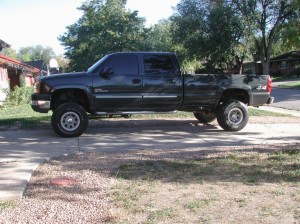
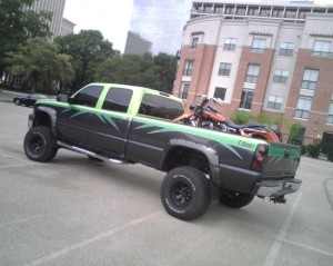
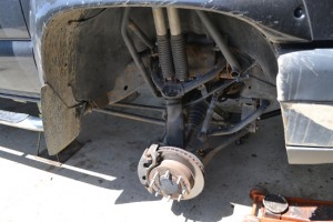
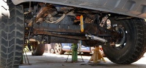
The truck on the day we got it
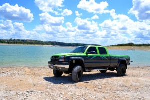
truck needed a month or so to get into shape for its job hauling projects across the USA.
after a few years and 120,000 miles of hard use its still doing well other than repeated IFS issues.
its taken almost 3 years of collecting parts and calculating how we would go about the Solid Axle Swap. here are a few of the key parts used to complete this project.
Parts for this build:
- 89′ ford kingpin DANA-60
- north west fab crossover steering kit
- north west fab slip yoke eliminator kit
- 3″ sway-a-way coil over shocks (14″ travel)
- lots of 3″ ballistic fab joints
- psc hydro assist
- ABS tone rings from DLUX fab
- longfield Spindle Bushings
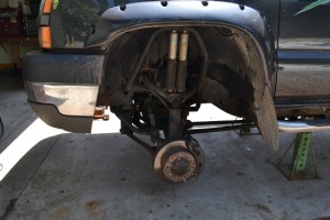
kicking things off is removing the IFS
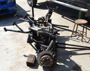
this is the IFS and front axle after removing it from the truck
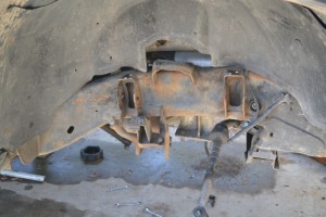
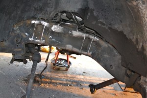
with the IFS off the truck we were able to start removing left over brackets.
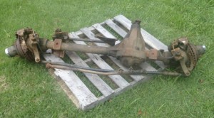
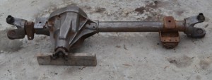
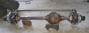
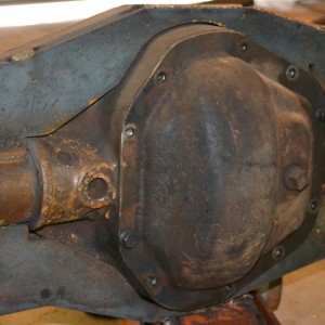
with the IFS has removed, we shifted focus on getting the Solid Axle ready. this is what the axle looked like when we took delivery of it.
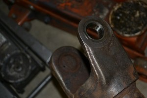
here you can see the king pins on top of each of the inner “c”s. these are held in place with 600 lb/ft of torque.
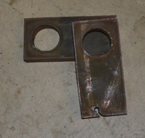
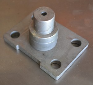
to replace the old king pins we used these King pin removal plates that are made with our CNC machine, they are cut from 1/2″ thick steel plate.
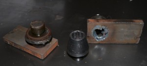
to remove the king pins simply weld the steel plates to the top of the king pin and use a sledge hammer to knock them free.
amazing, after 23 years the threads are rust free.
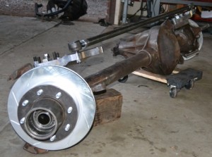
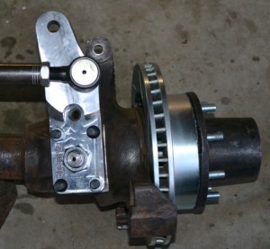
after removing its factory spring and shock mounts from the Solid Axle it is test fitted with the new high steering setup
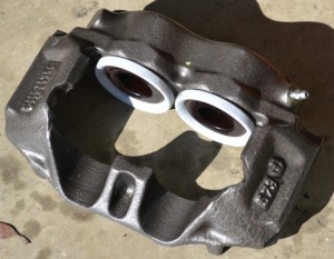
we chose to use cardone rebuilt calipers
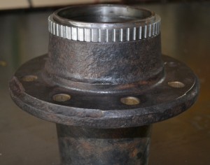
here is the stock ford hub after being machined and having the ABA ring pressed onto it. this will allow the factory ABA to function properly on the Solid Axle.
this shows how tight the fit is for the retrofit ABA sensor setup.
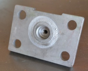
this is the new lower king pin, its built with the grease fitting recessed so it wont get damaged off-road. these are heat treated after being tig welded.
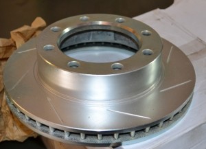
R1 supplied rotors for this project
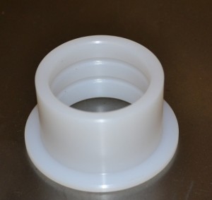
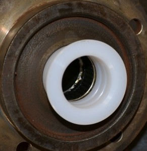
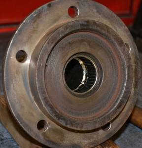
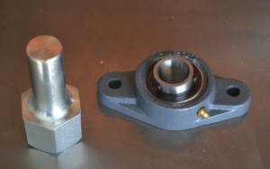
Longfield makes the bushing to replace the bearing inside the spindle for the axle stub.
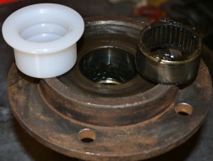
here you can see the old bearing sitting next to the replacement bushing.
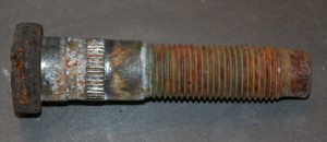
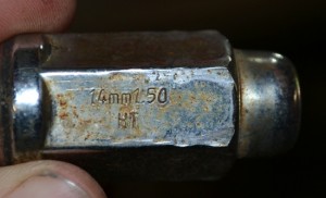
while upgrading the axles we chose to swap all 16 wheel studs over so they are the stock GM metric thread pitch. stock ford style stud
GM uses 14mm x 1.50 studs.
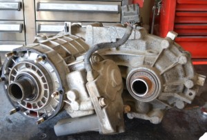
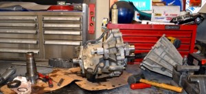
one major hurtle to overcome is changing the stock transfer case from having a slip style front output shaft to a fixed style output shaft. this is the stock transfer case. the slip style front output shaft can be seen off to the right.
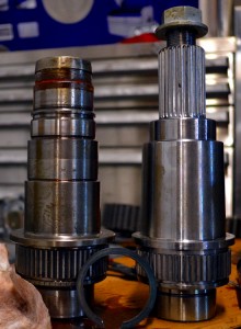
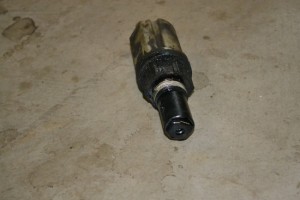
stock output shaft on the left, new output shaft on the right.
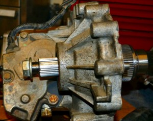
here is the new output shaft test fitted into the case half.
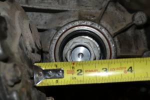
one issue with changing to the fixed style output shaft is its location being so close to the side of the main transfer case housing. this makes for a tight fit around the drive shaft.
here is the stock IFS selector motor, this is what engaged the front axles when in 4 wheel drive. it will need to be kept on the truck so the push button action of the transfer case will continue working properly with the Solid Axle.
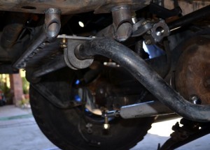
these are the start to an removable subframe. to take advantage of some existing holes in the frame and maintain clearance it was necessary to use this style of mount.
here is the finished subframe. it works as a brace for the frame and a mount for the subframe along with acting as a mount for the sector shaft brace bearing.
we chose to go with an PSC sector shaft brace setup. this is going to help take load off the steering gear box and eliminate slop in the steering.
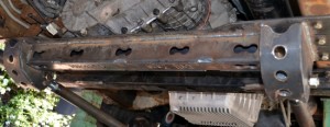
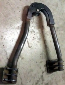
the crossmember for the radius arms was built from 1/4″ steel and both tig and mig welded. after being cut on the CNC system the main plate is bent on our 20 ton press brake and then put in a jig and welded.
the crossmember for the radius arms at the frame mounts to the trucks frame with 12 grade 8 bolts.
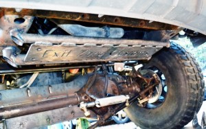
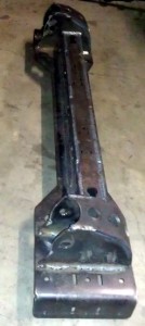
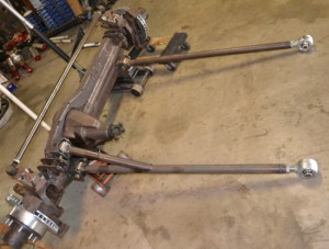
since we chose to design our own long travel radius arm suspension setup to go with the coilover shocks there was an issue of how to attach everything to the solid axle. this is what we came up with, it is an over and under axle truss that incorporates all the mounts needed to make the suspension and hydro steering work. the truss is cut from 1/4″ plate and has an brace inside of it that is welded on all edges.
we spent the time to map out the cast center section of the axle so we could keep the truss tight to the axle for clearance but maintain enough structure to add strength.
we installed a upper and lower truss onto the axle. this gives us plenty of locations for mounting the coilover shocks, radius and everything else needed to get this axle working properly.
after getting all parts tacked into place and test fitting them on the truck and cycling everything through its filed of motion this is what we had come up with.
The shock towers are built based off of CAD modeling using our DOM bender and Plasma CNC to achieve the strongest tower we could build with minimal material. there is very little room toward the top of the shocks location requiring exact fitment of the shock towers.
the new shock tower being test fit on the passenger side frame rail
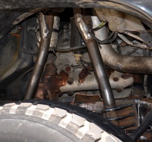
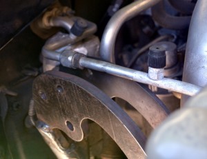
these coilover shocks are so tall that the shock towers have to be extra tall to the point they almost hit the hood. this photo shows how even the AC lines had to be taken into account when designing the shock mounts.
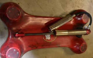
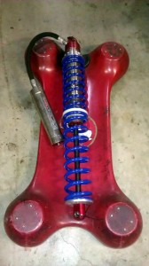
these 3″ bodied coilover shocks are some of the largest available on the market at this time
the coilovers will be running 2 springs per shock to get enough spring length and load capacity to handle the weight of the truck. fully extended these shocks are almost 40″ tall and weigh 38lbs with the springs and heard wear installed

